


By Garry Lancaster
Construction of the "classic" simple 8-bit interface
Because of the simplicity of this interface, there are very few components or connections required, so most people with access to a soldering iron should be able to construct it without too many problems.
Thanks to Frans van Egmond for details of the internal interface provided here (although neither he nor I accept any responsibility for any damage caused by the interfaces presented here).
PLEASE NOTE: I cannot build interfaces for other people!
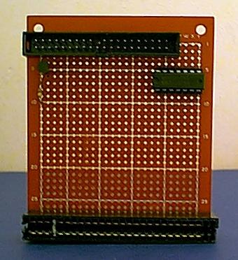
Here is a photo of the interface that I built, and use with my +3e:
Thanks must go here to Pera Putnik, who designed the original "simple" IDE interface; the interface presented here is almost identical, with just a couple of changes to the addressing, which should allow the interface to be compatible with more other hardware.

Component List
You will need the following components to make the IDE interface:
- 40-pin IDC connector
- Spectrum edge connector
- 74LS10 chip
- BC327 transistor
- 100K resistor
Additionally, you will need a small board to mount the circuit on.
If you wish to build the popular internal interface, instead of the Spectrum edge connector you will require a 40-pin socket for the Z80 chip (with long legs if you can find one). In this case, the Z80 is removed from its socket and plugged into the interface card socket; the whole thing is then plugged into the Z80 socket in the +3.
Building the interface
A schematic for the interface is shown below. Unlike most schematics, I have included all the connections you need to make, so you do not need to know much about electronics to build the interface; you just need to be able to use a soldering iron. Colour-coding is used where confusion might otherwise arise.
Pin numbers for both the Spectrum and IDC connectors are listed. Additionally, connections for the Z80 socket are given if you wish to build an internal interface, rather than an external one. For the Spectrum connector, these correspond to the diagram at the back of the +3 manual. For the IDC connector, pins are numbered 1,3,5...39 along one side of the connector, and 2,4,6...40 along the other, with pins 1 & 2 being adjacent. For the Z80 socket, if you look at the chip with the notch at the top, pins are numbered 1-20 down the left side, and 21-40 back up the right side to the top.
PCB Layouts
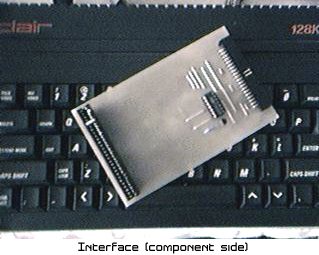
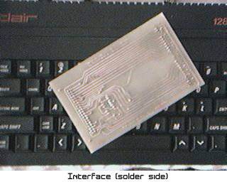
Steve Smith has spent some time producing some PCB layouts for both the internal and external 8-bit interfaces. The external interface he has built from this looks very smart! If you're able to produce your own PCBs, Steve has kindly provided full details of this and layout files in several formats, together with some nice pictures of the interface and his final setup.
Grab the entire archive (layouts, instructions and piccies) in this file: Plus3eHD_Int.zip. In the meantime, here are some pics of the final product to whet your appetite!
If using the system with the simple 8-bit interface (rather than one of the 16-bit hard-disk or compactflash interfaces), the following limitations also apply:
- Formatted hard disk capacity is half nominal
- CD-ROMs and other ATAPI devices cannot be supported
The current software release also has the following flaws and limitations, which may be resolved in later versions:
- Maximum partition size of 16Mb (+3DOS would allow 32Mb max)
- Only two hard-disk partitions can be mapped to drives at the same time
- No support for CP/M with hard disks
- INPUT # command doesn't yet work correctly with file channels (although this can be simulated using the NEXT # command)
- Multiface 3 can only save snapshots to floppy disks. Other snapshot devices (eg RamJet) will have the same limitation, or may be incompatible.